2. Computer aided design (CAD)#
Let the 3D fun begin! I dived into the world of 2D and 3D design using CAD tools. The goal was to design a “LEGO“piece that’s not only flexible but can lock onto other pieces.
Downloading Inkscape#
Go to the module 4 for more info
Downloading FreeCAD#
It is a free and open-source 3D modeling tool. It’s great for creating precise designs, especially for engeneering and mechanical projects. I didn’t try it but we got a sneak peek during class.
Downloading OpenSCAD#
It’s a 3D design tool that’s all about creating models through code. Instead of drawing shapes, you write scripts that define the geometry and features of your design. It’s perfect for making complex parametric models. In short, you type some code, and watch your ideas come to life in 3D.
Problem with OpenSCAD#
I ran into a little problem with opening OpenSCAD on my Mac because it wasn’t registered by a known developer. But no worries! Here’s how I bypassed that :
- Go to settings
- Select Privacy & Security
- Go to security, click open
- Click open anyway and that’s it!
Learning how to use it#
- I started by following this tutorial by Nicolas De Coster.
- The cheat sheet has all the usefull functions to start a project.
OpenSCAD lets you create basic shapes with just a few lines of code. HEre are a few I played around with :
- CUBE
cube([x,y,z]);
- SPHERE
sphere(radius);
- CYLINDER
cylinder(radius1,radius2,high);
- TRANSLATE
translate([x,y,z])
- ROTATE
rotate([angle=, vector_argument=[x,y,z]])
- for LOOP
for(i=[start_value:step_value:end_value]);
translate([x,y,z])
replace x,y or z by i * UNION
Union()
- DIFFERENCE
difference()
- HULL
hull()
- MINKOWSKI
minkowski()
Let’s test some codes#
1. Define parameters#
Why is it important to define your parameters?
It’s like creating cheat codes for your model, easy, fast and customizable!
//parameters
$fn=50;
a=15.8;//longueur
b=31.8;//largeur
c=9.6;//hauteur
e=1.8;//hauteur au dessus
f=3.9;//du bord au centre
g=8;//separation centres
i=4.8;//diametre
2. Coding#
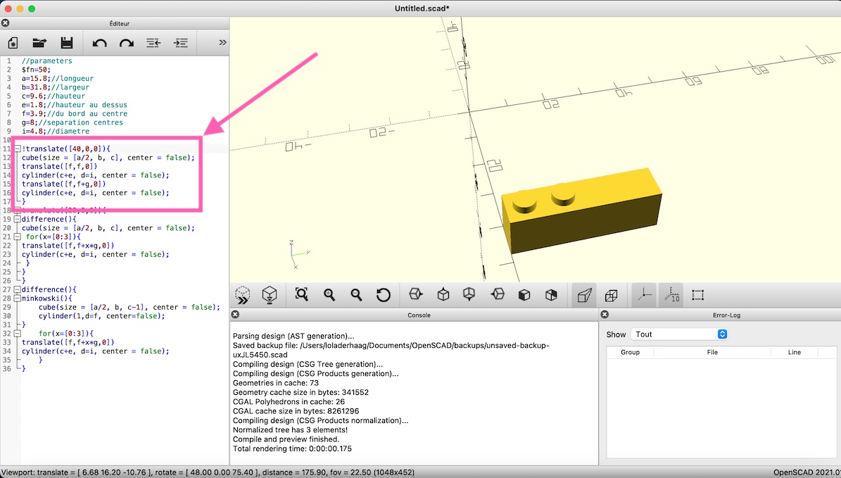
- Test 1 : basic lego brick
translate([40,0,0]){
cube(size = [a/2, b, c], center = false);
translate([f,f,0])
cylinder(c+e, d=i, center = false);
translate([f,f+g,0])
cylinder(c+e, d=i, center = false);
}
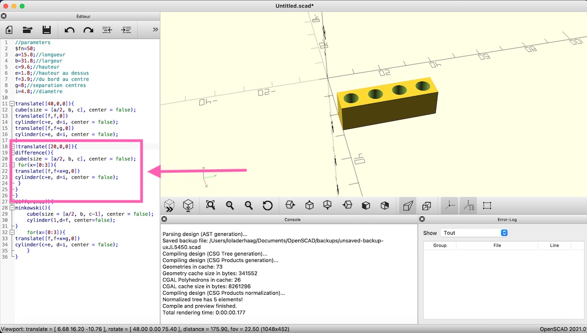
- Test 2 : cube with holes
translate([20,0,0]){
difference(){
cube(size = [a/2, b, c], center = false);
 for(x=[0:3]){
translate([f,f+x*g,0])
cylinder(c+e, d=i, center = false);
 }
}
}
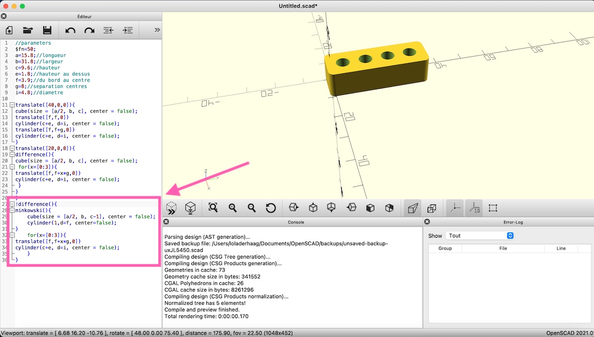
- Test 3: cube with holes + rounded corners
difference(){
minkowski(){
    cube(size = [a/2, b, c-1], center = false);
    cylinder(1,d=f, center=false);
}
    for(x=[0:3]){
translate([f,f+x*g,0])
cylinder(c+e, d=i, center = false);
    }
}
Designing my Flexlink#
After getting the hang of things, I read some blog posts from other students (by Pauline Mackelberg , by Morgan Tonglet) to spark inspiration, and here is how I started designing my Flexlink.
1. Set my parameters :
//parameters
$fn=30;
h=10;//height
a=25;//arc
t=3;//thickness
b=5;//diameter
c=2;//distance arc and piece
2. Coding
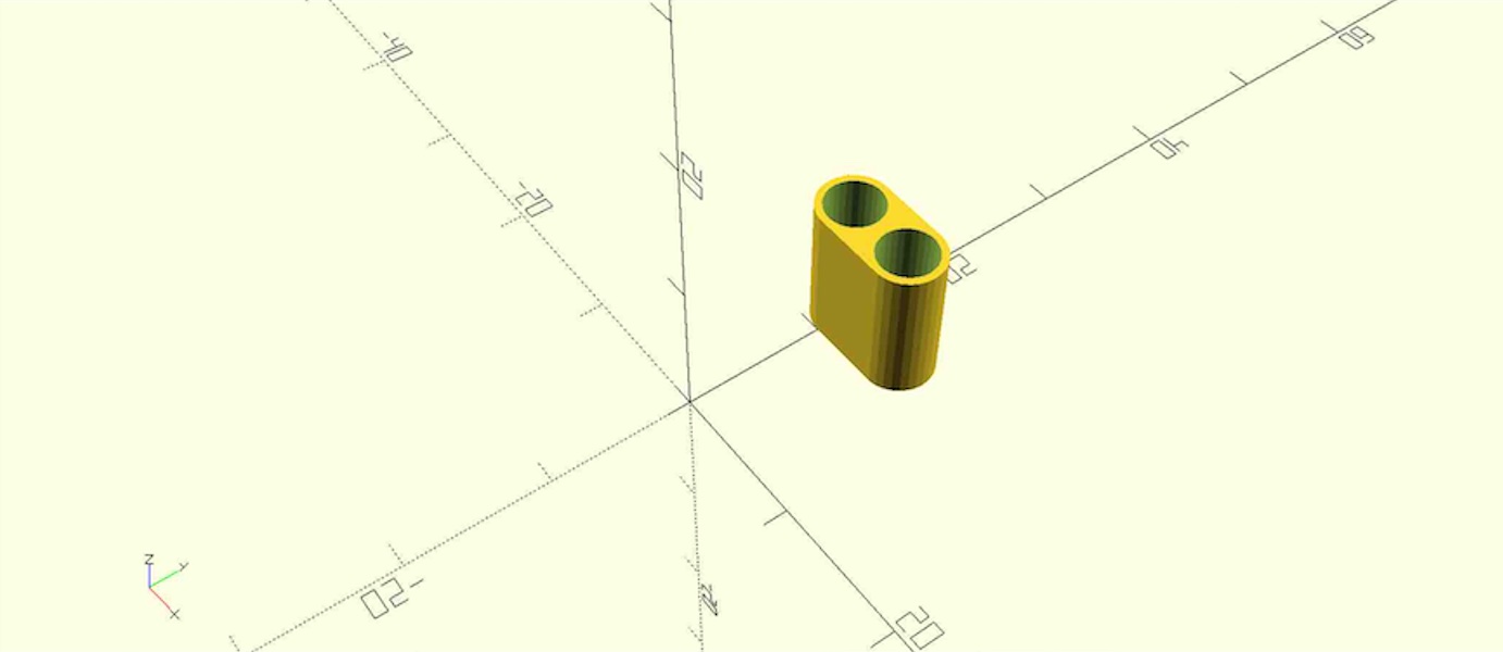
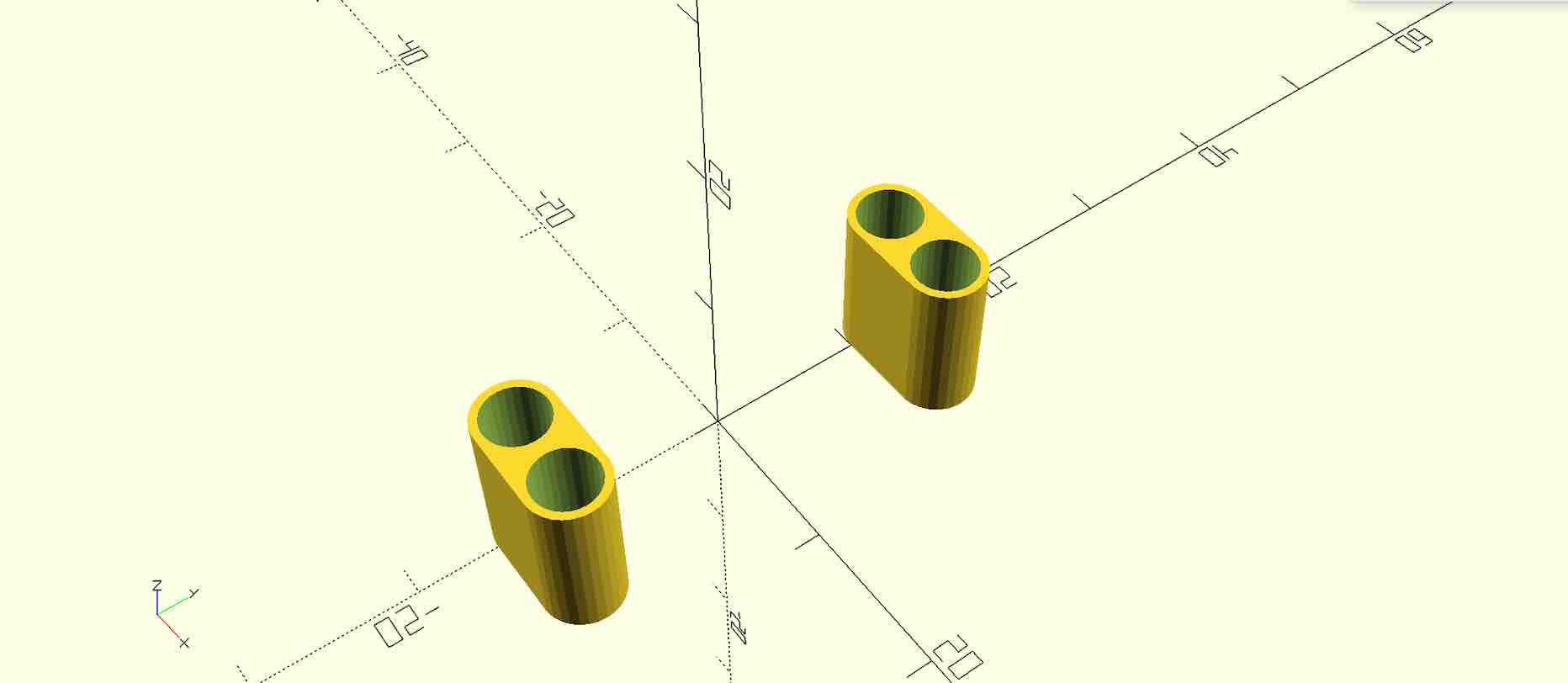
- piece 1 : starting simple
I started with two cylinders, hulled them. Then subtracted two smaller cylinders.
//piece 1
    difference(){
        hull(){
            translate([0,a/2,0])
            cylinder(h,d=b,center=false);
            translate([b,a/2,0])
            cylinder(h,d=b,center=false);
        }
        translate([0,a/2,0])
            cylinder(h,d=b-1,center=false);
            translate([b,a/2,0])
            cylinder(h,d=b-1,center=false);
    }
Here is what I got :
- piece 2 : copy and modify
I tried creating a module to just duplicate the first piece but I couldn’t make it work. Instead, I did the same as the piece 1, subtracted two small cylinders from two big cylinders previously hulled.
//piece 2
    difference(){
        hull(){
            translate([0,-a/2,0])
            cylinder(h,d=b,center=false);
            translate([b,-a/2,0])
            cylinder(h,d=b,center=false);
        }
            translate([0,-a/2,0])
            cylinder(h,d=b-1,center=false);
            translate([b,-a/2,0])
            cylinder(h,d=b-1,center=false);
    }
Here is what I got :
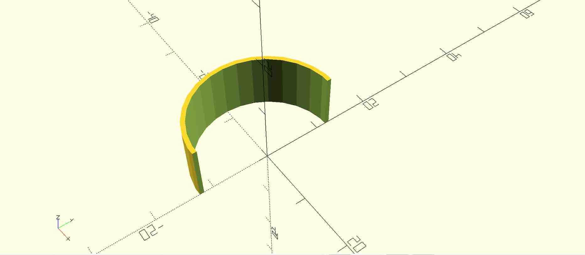
- arc
Now I needed something to bind the two pieces, I made an arc by subtracting a small cylinder from a big one. At that point, I had a circle with a hole inside but I only wanted half a cirlce so I subtracted a cube from the circle previously made.
//arc
difference(){
    difference(){
        cylinder(h,d=a,center=false);
        cylinder(h,d=a-t/2,center=false);
    }
    translate([0,-a/2,0])
    cube([a,a,h]);
}
Here is what I got :
- Problem
Once every part was done, I combined everything and a problem occured when aligning them.
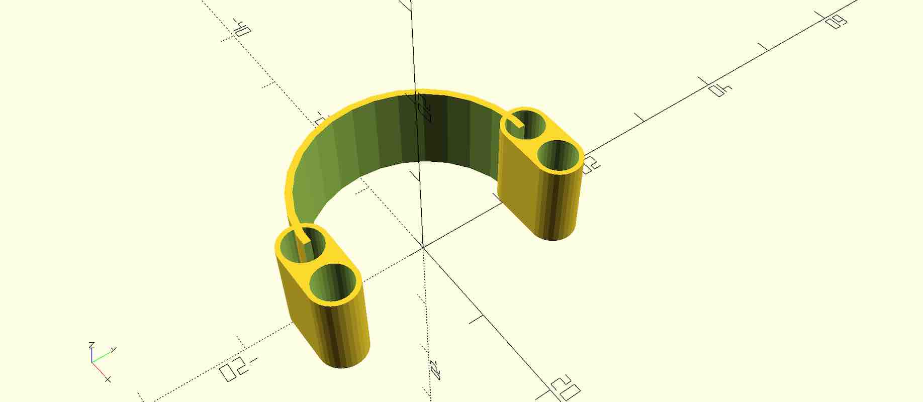
But with a litlle adjustment using the translate command, everything fit together perfectly.
translate([c,0,0])
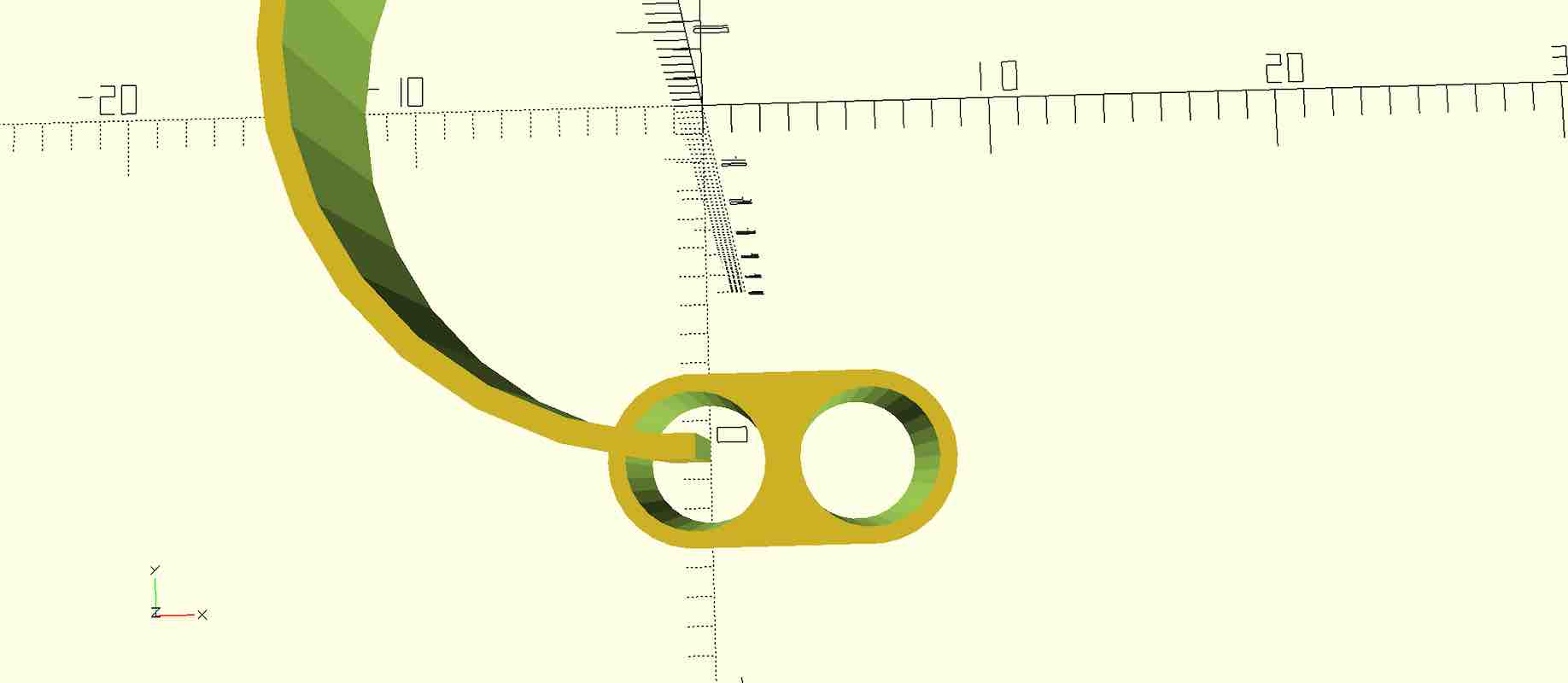
Here is my finished flexlink :
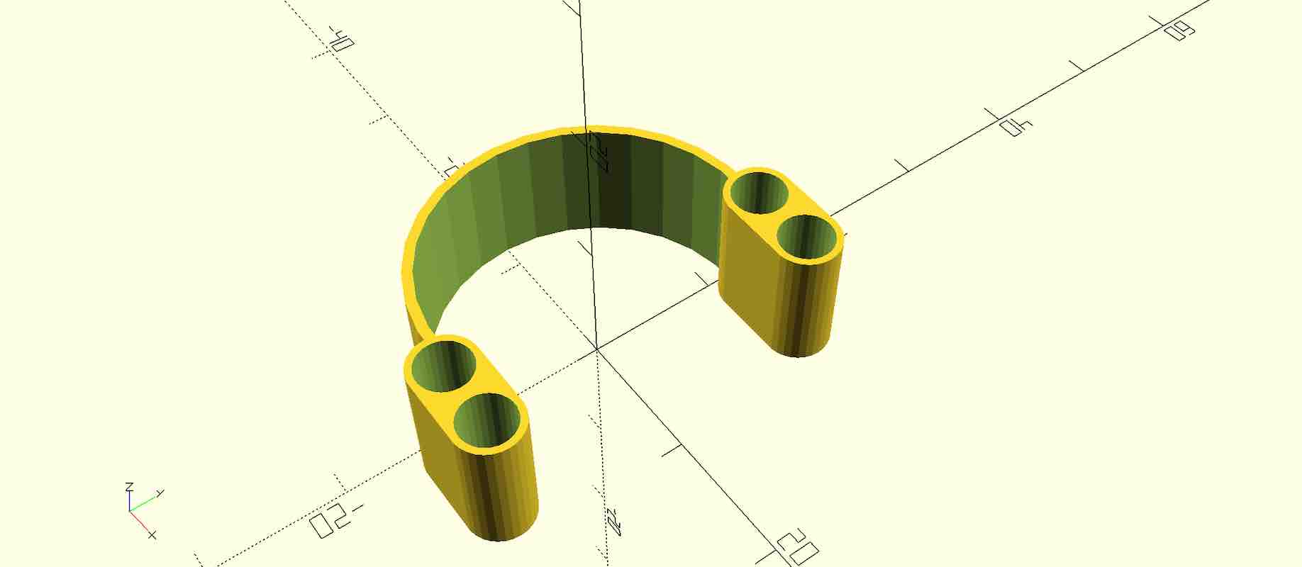
You can find the complete code here.
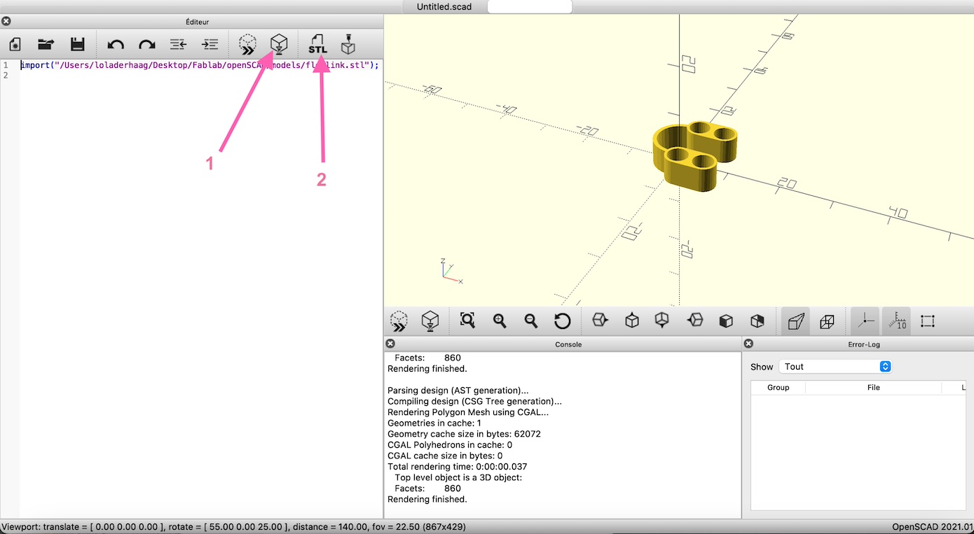
Exporting the Design#
Once the design was complete, I exported it by rendering and saving the STL file. Super easy:
- Render it
- Click on the STL icon
- Save it in your files
Useful commands#
Put in front of a row :
| symbol | action |
|---|---|
| % | makes it transparent |
| # | makes it red |
| * | removes it from the model but not from the code |
| ! | it’ll only be shown |
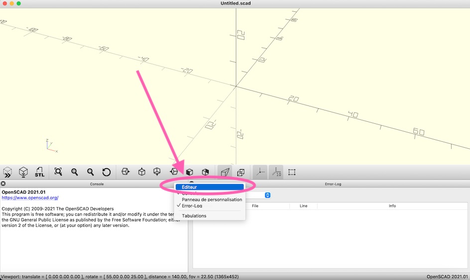
Problems#
-
I accidently closed the editor text and didn’t know how to open it again, well… now I know. You just have to click on the trackpad with 2 fingers on “console” or “Error-log” and just click on “editor”.
-
If it says there is a syntax error just try adding “;” or “{}”.
Licensing my work#
When you finish your design, you’ll want to license it to share with others. You can use a Creative Commons (CC) licence to do so.
This text must be added at the top of the code. Here is an example :
// File : flexlink.stl

// Author : Derhaag Lawra

// Date : 13 october 2024

// License : CC BY-NC-SA 4.0 Creative Commons Attribution-NonCommercial-ShareAlike 4.0 International
If you use someone else’s code, it’s important to cite the original work by addind a field Credits to the license.
Flexlinks kit#
After all that, I went on Thingiverse to explore more ideas of Flexlinks and found this one that looks really nice but I don’t understang openSCAD enough yet to do it myself. So I just copied the code and made some parameters changes.
Now that your designs are all set and exported, the 3D printing adventure isn’t happening just yet, but don’t worry it’s coming up in the next module!